
Evolution of the M1 Garand Rear Sight
![]() April 27th, 2021
April 27th, 2021
![]() 7 minute read
7 minute read
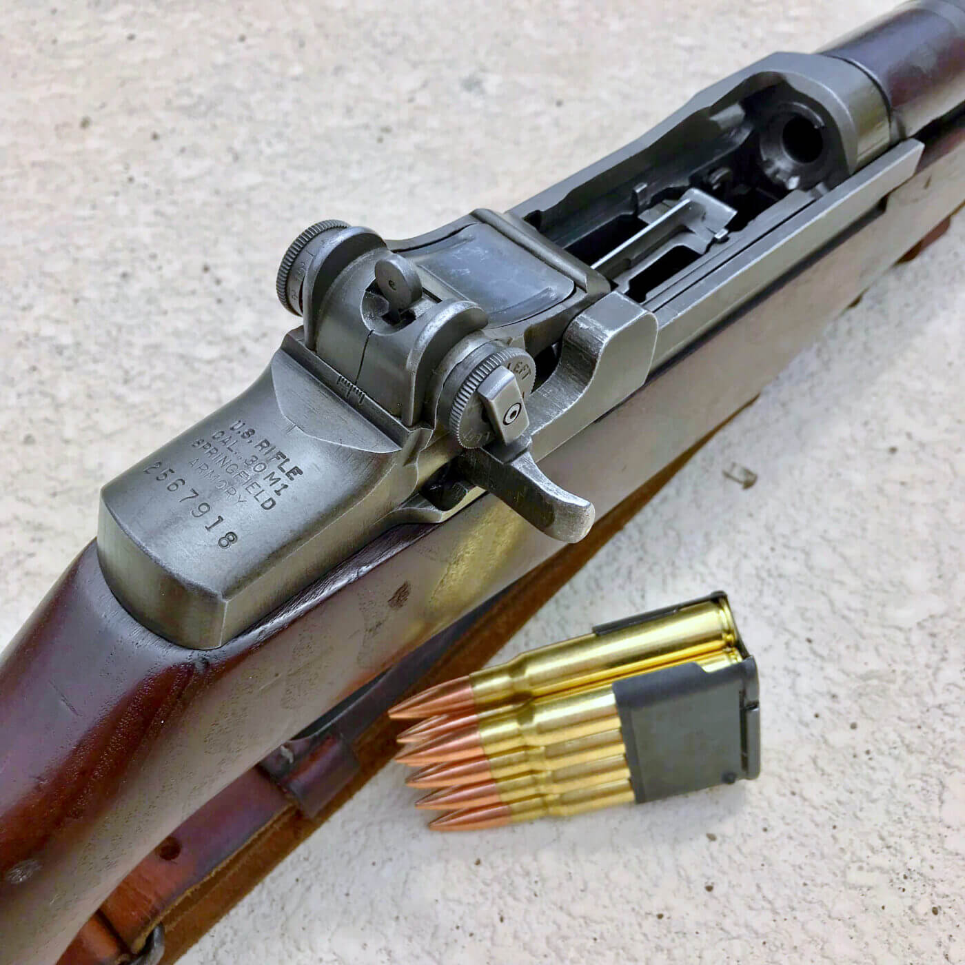
The U.S. Rifle Caliber .30 M1, brainchild of John C. Garand, was an impressive feat of small arms engineering at the time of its adoption. The design became an icon of the U.S. infantryman from World War II to the Korean Conflict and beyond.
One of the design features to continue from the first M1s to later rifles was the rear sight assembly. From the M1’s adoption to the M14 and today’s M1A, the rear sight design went through several minor changes and modifications.
When the M1 Garand rifle was first adopted in 1936, its rear sight was one of the many notable features of the rifle that was a significant departure from what the U.S. infantryman had used prior. The Springfield M1903 and M1917 Enfield rifles used ladder-style sights that had to be raised in order to set a specific range.
The M1 rear sight on the other hand uses only a single peep aperture within a robust housing, with a knob on the left for elevation adjustment and a knob on the right for windage. Both the elevation and windage knobs have specific measurement stops they interact with on the receiver. The adjustments have audible clicks, with each click representing 1 MOA, or one inch of adjustment on target at 100 yards.

The Flush Nut Design
The rear sight design itself is relatively simple, comprised of no more than 9 parts on the initial version. This included an elevation pinion, elevation cap, elevation cap screw, base, cover, aperture piece, windage knob, compressing spring, detent, and nut. The base acts as the housing for the aperture and knobs while the cover keeps out debris and secures the base to the action. The elevation pinion slides into the base and through the other side with the windage knob sliding onto it and screwing into the base. Some of these features like the base, cover, and aperture would only undergo minor simplifications for ease of production.
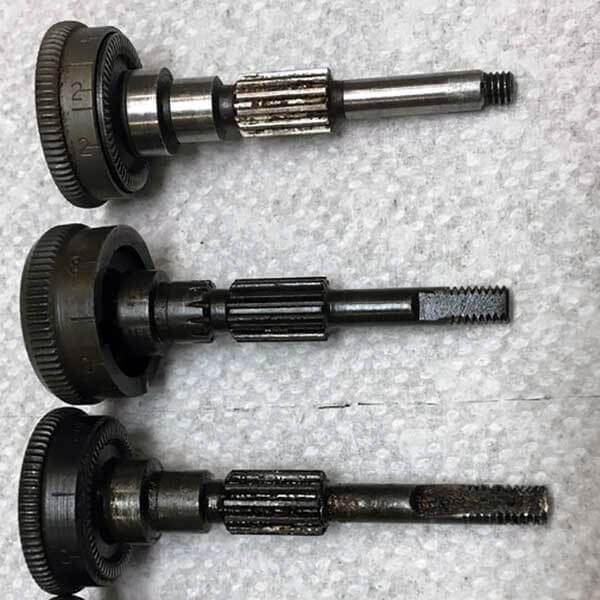
From adoption to the first year of U.S. involvement in World War II, the M1 rear sight remained largely unchanged. The early production parts were finely machined, including the knobs with checkered edges, the base and aperture with parts numbers, and the cover with a part number and no reinforcing indents stamped in. The elevation pinion on these early sights, known as a “short pinion”, is flush with the edge of the windage knob with 6-40 NF threads.
The nut that screwed onto the pinion on top of the compressing spring and detent is also flush with the windage knob, earning it the nickname of “flush nut”. The elevation cap on the pinion variations up to the end of World War 2 is removable, allowing the user to find the desired elevation setting for a specific range and then re-attach it to the pinion at the correct graduation. These caps feature an arrow with the words “BATTLE RANGE” marked on the side, pointing to the 300 yard mark.
Changes to the rear sight design began with U.S. involvement in World War II. Parts were simplified to require less machining. There were some differences in the implementation of these changes between the two manufacturers of the M1 during World War II, Springfield Armory and Winchester Repeating Arms, so we will focus on changes made by the larger producer, Springfield Armory.
By mid-1942, some simplification had already taken place on the sights. The checkering on the knobs (except the elevation cap in some cases) was swapped in favor of knurling which was faster to machine yet still provided adequate grip. Part numbering was deleted and machining was simplified on the aperture, base, and cover.
The Locking Bar Design
One of the most noticeable changes made to the design at this time involved the flush nut. The flush nut began to cause problems in theatre. First, it required a specific tool to tighten it down. Second, it could be worked loose by adjusting the sight or worse, completely unscrew. This meant that the nut no longer put the needed pressure on the compressing spring and the adjustment knobs would become loose. If the flush nut fell off, the knobs would lose retention on the receiver measurement stops and free-spin. This resulted in a sight that could no longer hold a zero.
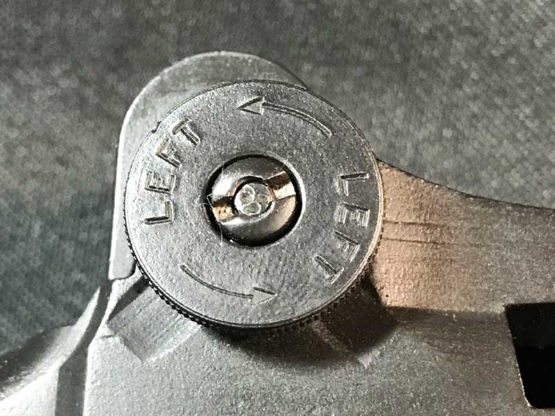
The issue of loosening flush nuts was a major flaw that would require a redesign of the knobs and compressing spring assembly. Instead of redesigning the assembly, a stopgap was implemented through the introduction of a locking bar to replace the flush nut. This locking bar, or lock bar, screwed onto the elevation pinion and put pressure onto the compressing spring like the flush nut, except it sat on top of the windage knob and could be tightened down by hand. With the lock bar is loosened, elevation and windage adjustments can be made. When tightened, the lock bar completely locks both knobs in place. This helped keep the sight together and retain zero more effectively than the previous flush nut.
The first iteration of the lock bar, known as the Type 1, mounted onto the same short pinion as the flush nut with 6-40 NF threads. It was made of a single piece of rectangular steel with rounded edges to match the curvature of the windage knob. Despite these, there were still issues. The Type 1 lock bar could still be unscrewed off the pinion. The short pinion only had a small track of thread for the Type 1 to screw onto, with no way to stop the lock bar from being completely unscrewed. To correct this, the pinion was lengthened and more threads extending past the windage knob. The threads were changed in pitch to 8-36 NF and the tip of the pinion was hollowed so that the lock bar could be staked. This resulted in the “long pinion” Type 2 locking bar, introduced by the beginning of 1943.
The Type 2 lock bar shared all of the same features as the previous Type 1 in terms of function. Type 1 and Type 2 lock bars externally appear similar, with the only real change being thread pitch. Since it could be staked, the Type 2 didn’t have the risk of completely unscrewing and falling off. The Type 2 locking bar was used in Springfield Armory M1 Garand production from 1943 to mid 1944 when it was replaced by a slightly simplified version, the Type 3. The Type 3 lock bar uses the same pinion and thread pitch as the Type 2, with the only real difference being a change from rounded edges to squared edges and coarser machining.
The T105 Design
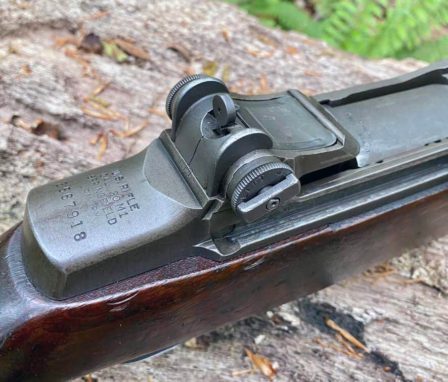
To address the problem initially encountered with the flush nut without limiting the ability to make adjustments on the fly like the lock bar, the T105 was introduced. The T105 is comprised of a redesigned pinion and knobs that negate the need for a nut or lock bar to put pressure on the compressing spring housed in the windage knob. Instead, the compressing spring was redesigned and relocated into the elevation knob, which no longer had a removable cap like the earlier versions.
A large screw on the head of the elevation knob controls the tightness of the sight and allows for the knob to still be rotated to the proper range setting like the earlier cap design. The windage knob slides onto the pinion like the previous iterations, but instead of an independent nut for tightening down on top of a detent and spring, has a captured nut that secures it to the pinion. The knobs were also enlarged to provide a better grip than previous versions.
Live The Armory Life. The latest content straight to your inbox plus an automatic entry to each of our monthly gun giveaways!
The T105 was not implemented until after the war, replacing the older designs in new M1 production during the 1950s to the end. The T105 pinion and knobs were also used to replace the older sets on rifles that were re-arsenaled in the post-war period, being completely compatible with the earlier sight bases and apertures. The T105 knob and pinion set is the most common type found on surplus M1s today.
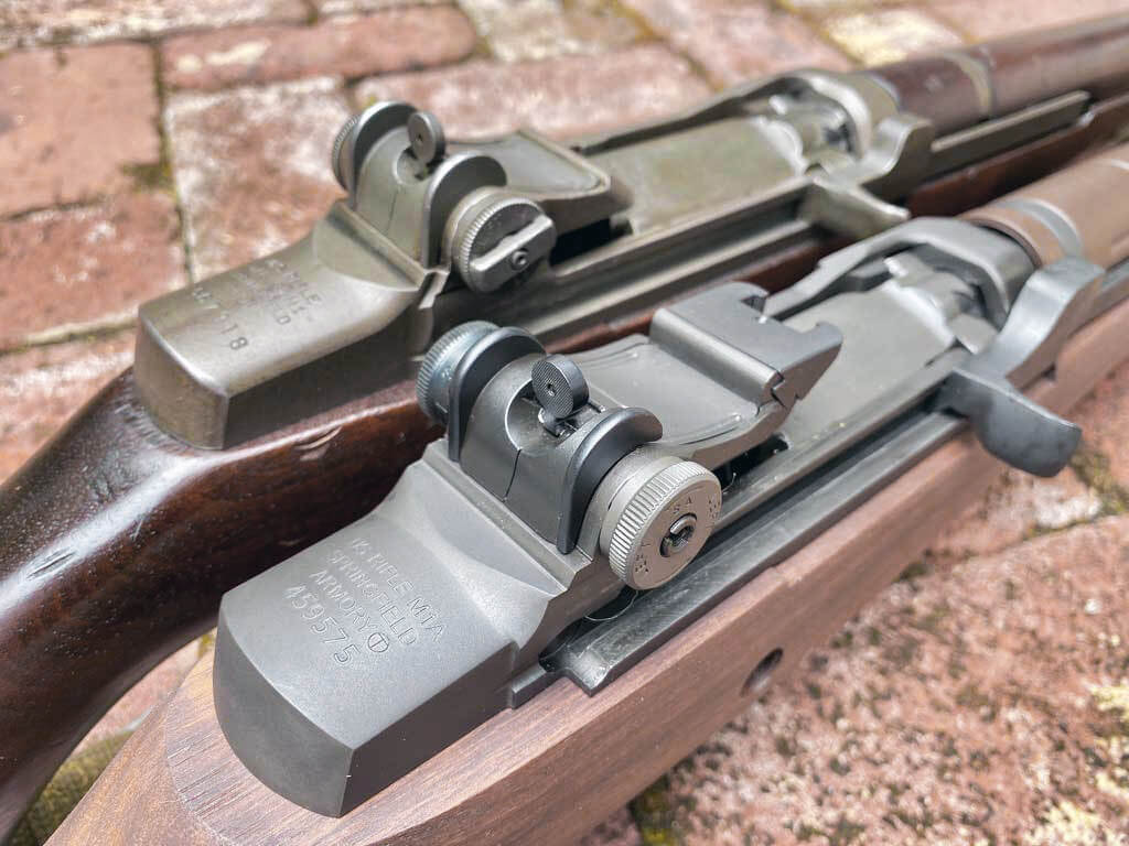
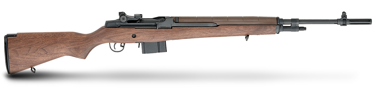
The T105, sight base, aperture, and cover design were carried over onto the design of the M14 gun and is one of the few parts that are completely interchangeable between the M1 and M14. The only major difference is that the range increments on the elevation knob for the M14 were changed from yards to meters, and is indicated so with a large “M”. This is the same rear sight design found on new production M1A rifles from Springfield Armory today and is a continuation of the M1 pedigree.
Editor’s Note: Be sure to check out The Armory Life Forum, where you can comment about our daily articles, as well as just talk guns and gear. Click the “Go To Forum Thread” link below to jump in!
Join the Discussion
Featured in this article
Share


Continue Reading
Did you enjoy this article?

 98
98
Springfield Armory® recommends you seek qualified and competent training from a
certified instructor prior to handling any firearm and be sure to read your owner’s manual. These
articles and videos are considered to be suggestions and not recommendations from Springfield Armory. The views
and opinions expressed on this website are those of the authors and do not necessarily reflect the
views and opinions of Springfield Armory.
Product prices mentioned in articles and videos are current as of the date of publication.

Hayden A. Foster
Hayden is an Air Force brat and grew up moving across the country. He has a degree in History from the University of Alabama and has a long-standing passion for military and small arms history. Hayden has written for t he NRA's American Rifleman as well as the World War II Magazine in the past. He was recently the Assistant Curator for the Institute of Military Technology in Titusville, Florida, and is continuing to deepen his knowledge for his passion.
